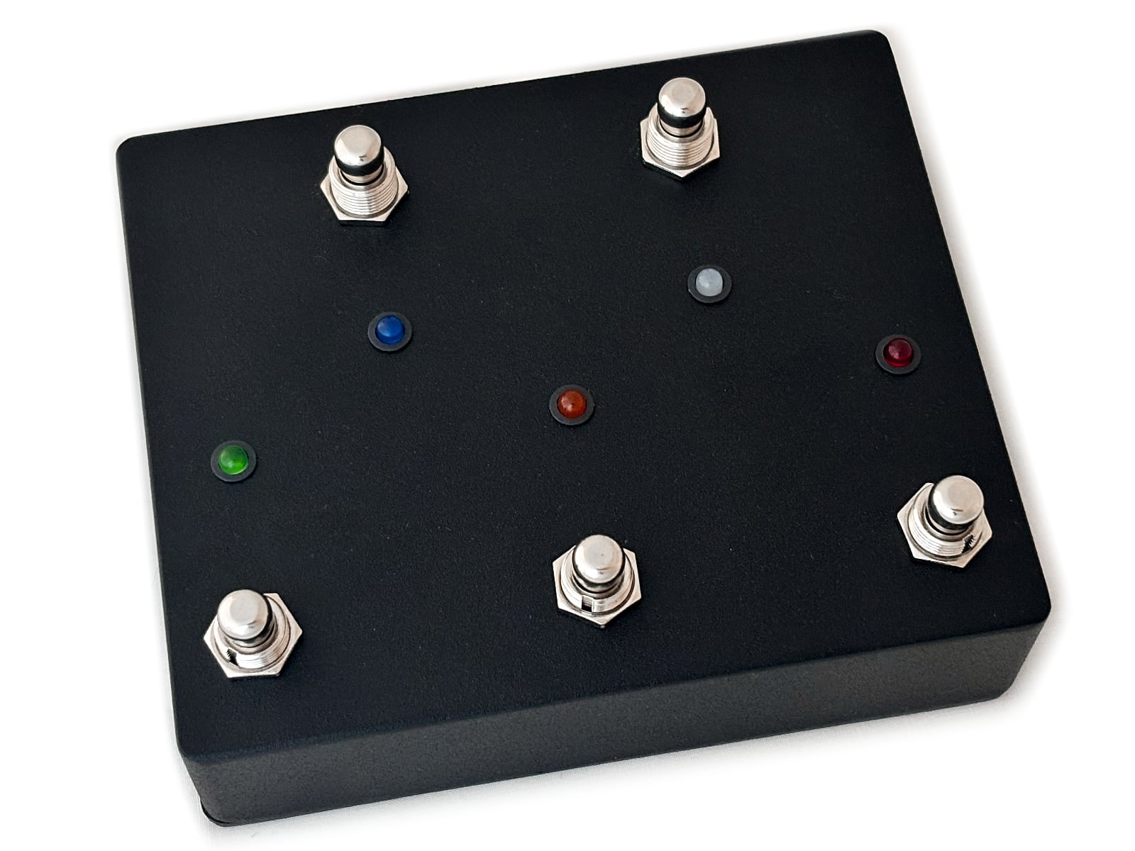
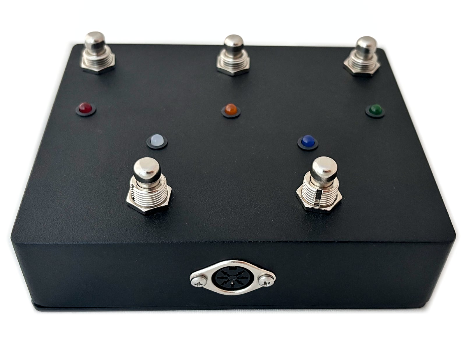
For years we offered a limited version of the Mesa Bigfoot+ named the Yeti which only had buttons for the three channels. This allowed us to make use a tiny enclosure but at the expensive of losing the Solo and FX Loop features. We finally have available a small run of our 5-button version of the Yeti supporting three channels, Solo, FX Loop, with bright LEDs and a black enclosing measuring 5.5″ x 4.5″. Email to check availability.
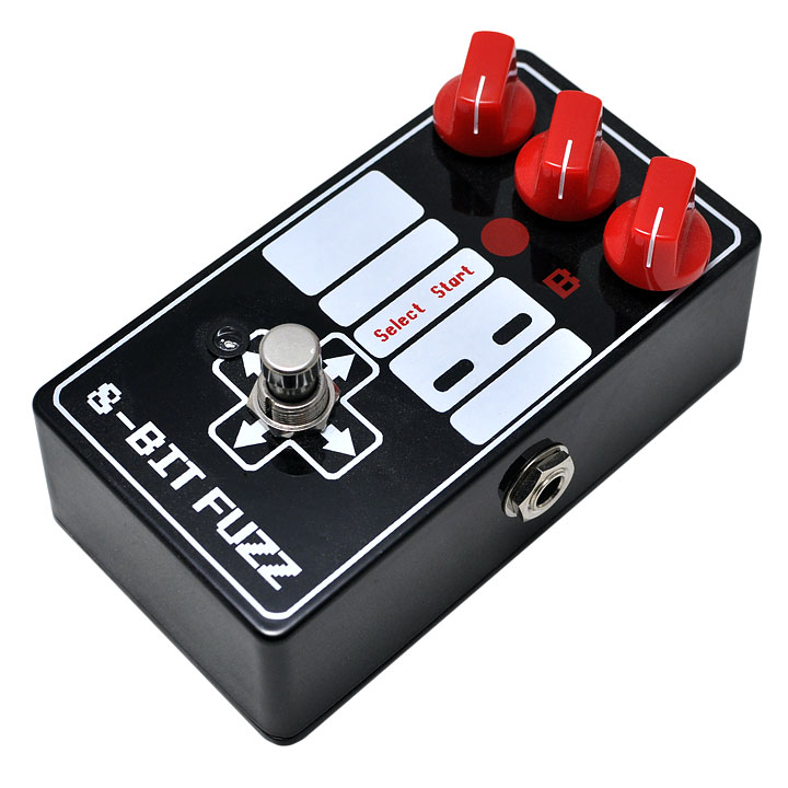
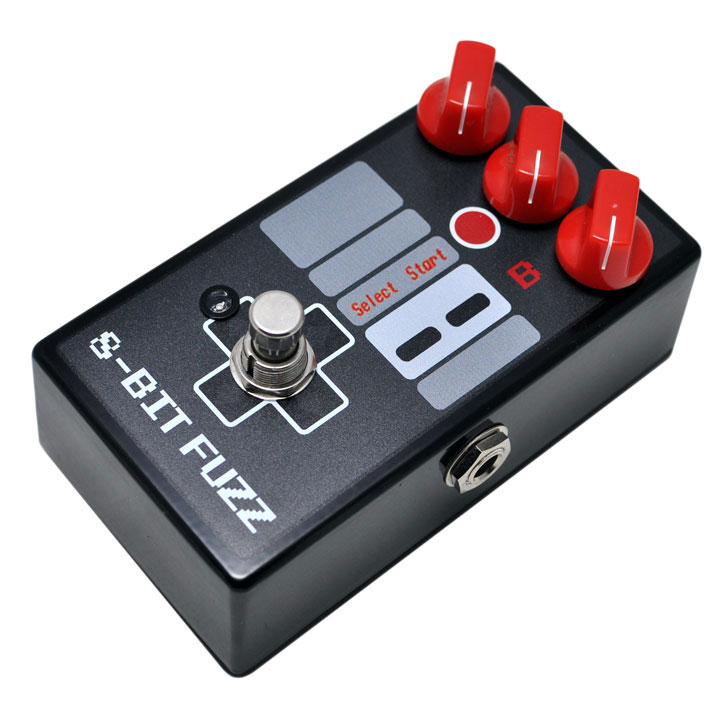
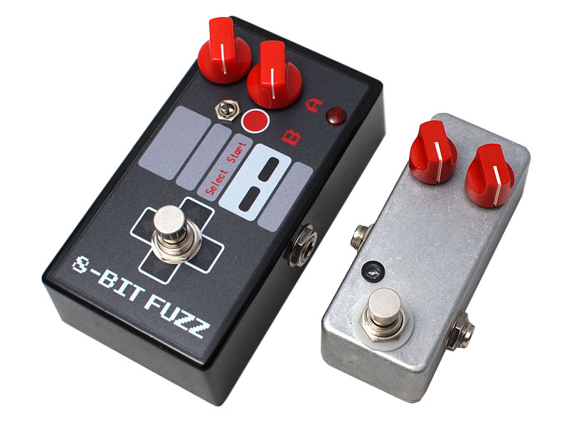
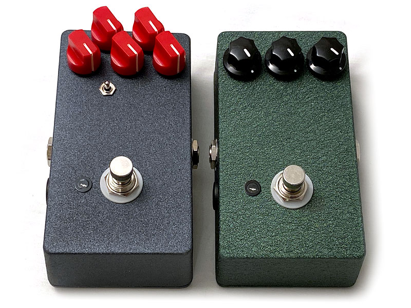
We’re a custom shop and have an in-house fuzz so naturally we’re going to have a lot of different versions over the years. The 8-Bit Fuzz started around 2002 as a glitch fuzz inspired by the chip tune music coming out at the time. For the past 25 years we’ve been making a version based on the original circuit. If you need help dating your pedal this should provide a time frame. We offer services to restore and update any of the older versions to bring them in line with some of the features found on later models.
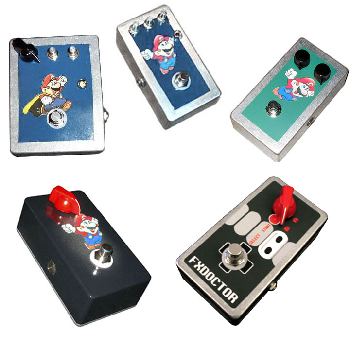
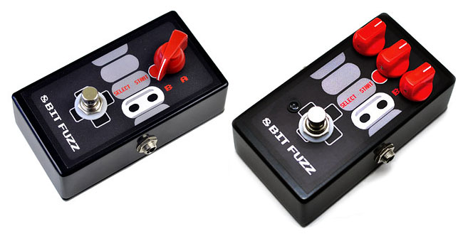
2002-2005: The first 8-Bit Fuzz (Top Left) started out as a 3 knob version with a caped Mario cut out from the instruction manual for Nintendo’s Super Mario World. Shortly after, depleted of Marios to cut out, we started using a printed version of capeless Mario in a smaller enclosure. I remember at the time the 3PDT foot switches on the market were expensive and unreliable resulting in us removing the LED. We briefly offered a 2 knob version and landed on the simplified one Volume knob version with the signature red knob (Bottom Left). In about 2004 we moved away from putting Mario on the pedal for obvious copyright infringement concerns.
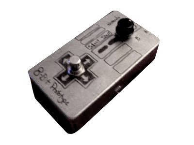
This 2004 prototype was hand drawn and shipped around as a mail-order demo unit.
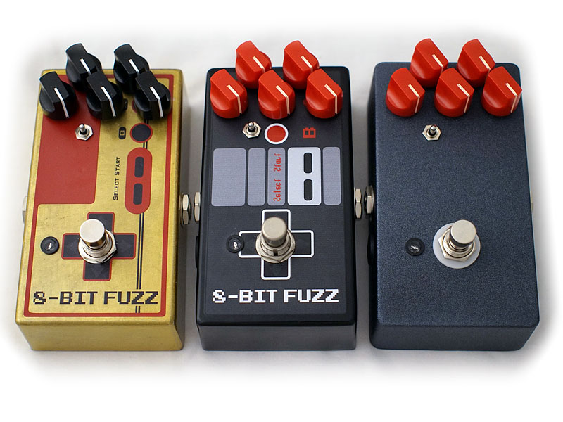
This is what became the standard 8-Bit fuzz in 2004. We started using a printed label for the top and I believe were selling for around $70 at the time.
A few years later we found a good supplier for painted enclosures and started offering these in 2007.
Around 2008 we switched over to using stickers instead of gluing on labels. These were much more durable. If you remember earlier, we removed the LED due to issues with 3PDT switches on the market but we brought it back and also added back in the Gain and Stability knobs. This was a transitional period while we were trying to balance price and performance. Eventually the single knob version was phased out and the 3-knob became the standard model.
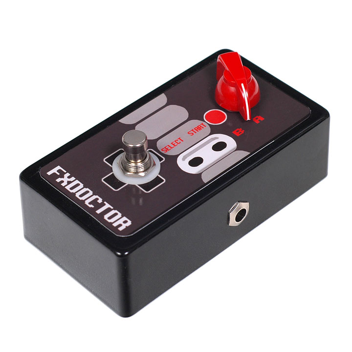
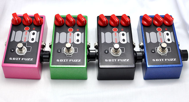
Our first serious attempt at launching this as a retail product was 2011 where we had the absolutely most cursed experience getting good looking enclosures from a now defunct supplier. The samples looked great but the product that shipped to us was almost entirely unusable. This gloss black and two color silk screened enclosure was one of the few that actually were assembled and sold.
This is our second attempt at a retail launch around 2013 using a different vendor that could do full-color UV printing straight onto the enclosure. The product looks significantly better and was our standard look for years.
For those not familiar with the pedal, the Gain and Stability knobs are designed to balance each other out. If you turn both all of the way up, the pedal self-oscillates. This is fine for online orders where we can show the expected behavior in a video and provide a user manual, but for a retail setting people were walking away confused as to how to use the pedal. Above is our attempt to make a “retail friendly” version that combines the Gain and Stability knobs in a way the prevents self-oscillation. Also a mini version for fun.
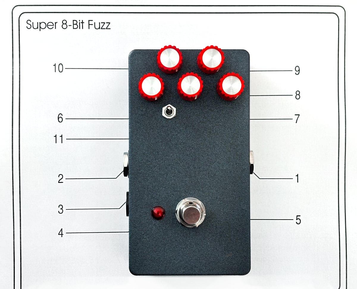
Now in 2015 we started offering the “Super 8-Bit” fuzz which has an added Cut knob, Focus knob, and a 3-way Mode toggle switch. This was offered alongside the standard model for a while but eventually we cut the lower tier 2 and 3 knob versions. This is the final version of the pedal; We love the evolution over the 13 years since the first one was assembled and consider this the best one we’ve built.
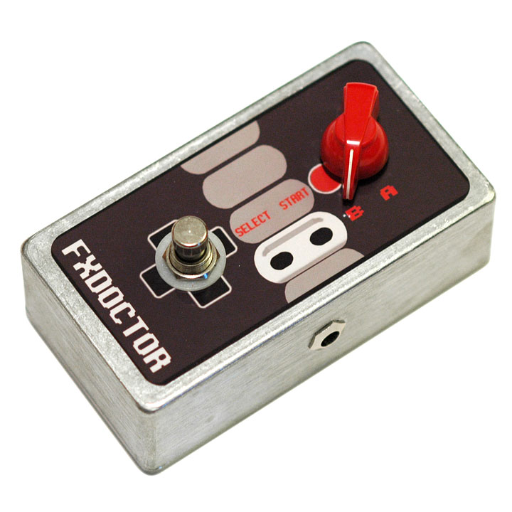
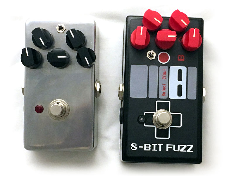
Suppliers can be finicky and stocking inventory can be complicated. We eventually moved to an unlabeled enclosure to keep the retail price down and free us from vendor constraints. This especially became an issue in 2020 when there were massive supply chain constraints. In addition to the lower cost, the textured silver powder coat is very durable.
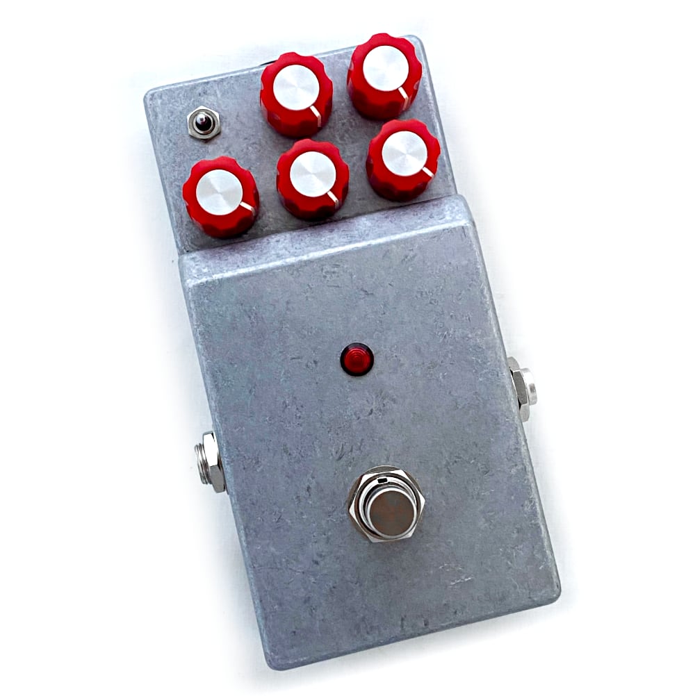
And this is the final version. We’ve switched to a red LED diffuser and put on some different knobs to make them easier to turn but otherwise the circuit has remained the same.
Below are some of the prototypes and limited editions we’ve offered over the years:
Here we have a run of 8-Bits with a volume cut knob on the right side. This was the inspiration to add it to the “Super 8-Bit” version which we later released. The height is just right where you can get a rubber cap from Dunlop/MXR and (gently) roll it up and down with your foot.
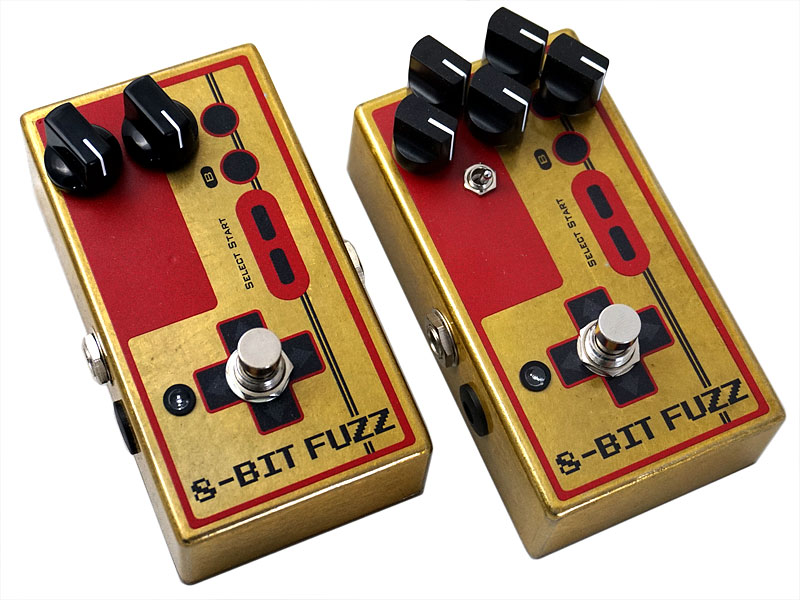
Here’s our 2015 limited edition Famicom version for the Japanese market. The gold finish is beautiful but can be problematic as it shows the blemishes of the aluminum casting underneath.
A prototype of when we were attempting to shrink the enclosure down from a 125-B to 1590b. Certainly possible but would require reworking the PCB and changing the knobs.
Another experiment at trying a different enclosure and knob layout. This 2023 prototype uses the Small Bear Bare Box which had some really nice features like a lower area to protect the knobs and access to the battery compartment with no tools required.
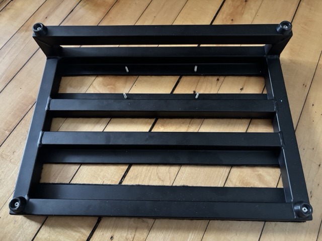
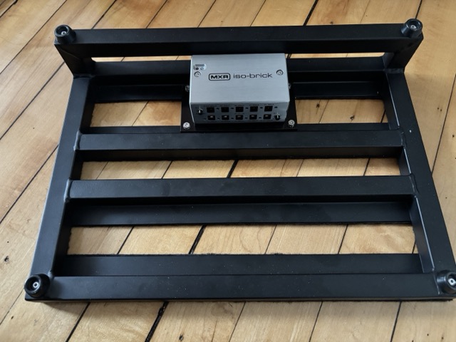
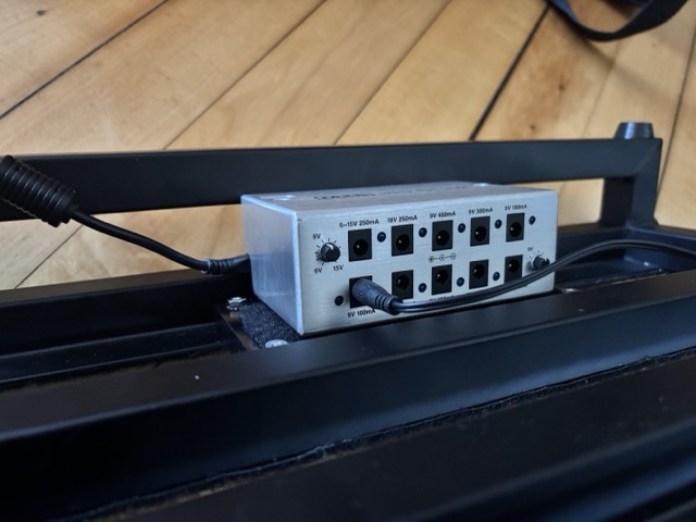
I’m a big fan of the Pedaltrain Classic Jr for being lightweight and having a reasonable stage footprint but the lack of mounting options for a power supply is really disappointing. This board can easily hold 10 pedals so it’s not unreasonable to want to use an isolated power supply rather than just daisy chaining the pedals. Here’s the materials I used to mount an MXR ISO-Brick -and what I’d do differently- if I were to do it again.
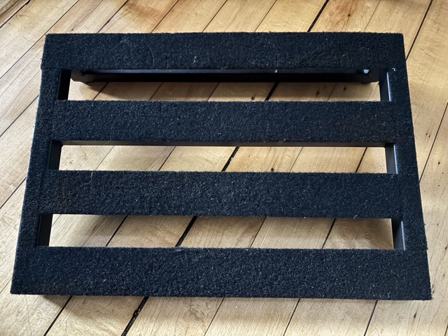
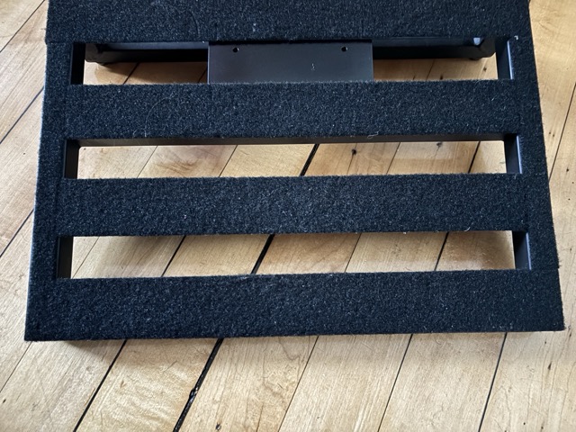
Here’s our starting point. Velcro already on the board so I made a few cuts where the mounting screws will go.
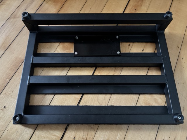
We’ll be using a piece of aluminum flat bar as a mounting bracket, so holes on the pedalboard are spaced to fit the flat bar. Here I used four #6 countersunk screws, 3/4″ in length because I had them around but any small screw will work here.
Mounting bracket was purchased from eBay- it’s a 1/2″ thick piece of aluminum flat bar that’s 3″ wide and 6″ long. Aluminum flat bar comes unfinished so plan on time to paint after drilling if you care about that. I needed about 3/8″ of clearance so the power cables will have clearance over the support bars so I went with a 1/2″ to be safe. I’d recommend getting a 0.125″ or .250″ plate and using spacers to get the correct clearance since this bracket is unnecessarily heavy. It’s attached using locking nuts.
Here’s a test fit of the ISO-Brick.
And here is a picture showing the cable clearance when using a 1/2″ thick mounting bracket.
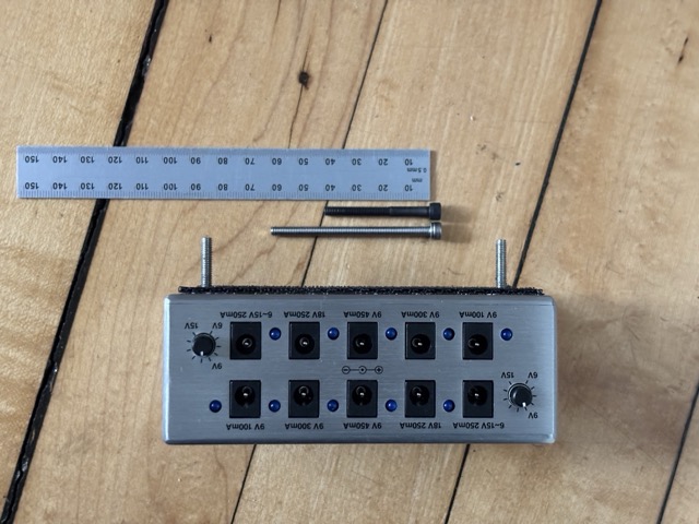
The ISO-Brick has two screws keeping the enclosure together. What’s really nice is these screws go straight through the chassis and if I replace them with longer screws I can use them as a mounting point for the power supply to the bracket. The stock screws are hex (allen) socket M4-0.7 x 40mm. I replaced them with stainless M4-0.7 x 60mm which gives the result above.
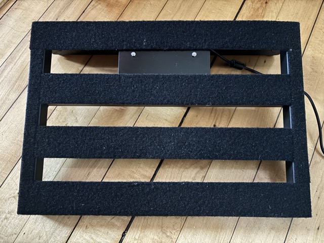
View from above of where it’s at so far. Bracket is attached, holes are drilled for the power supply mounting screws, and it’s ready to finish this up.
The power supply fits, there’s enough clearance for the cables, the power supply isn’t so tall that it touches the ground when the pedal is flipped over.
Two M4 nuts to hold the power supply to the bracket.
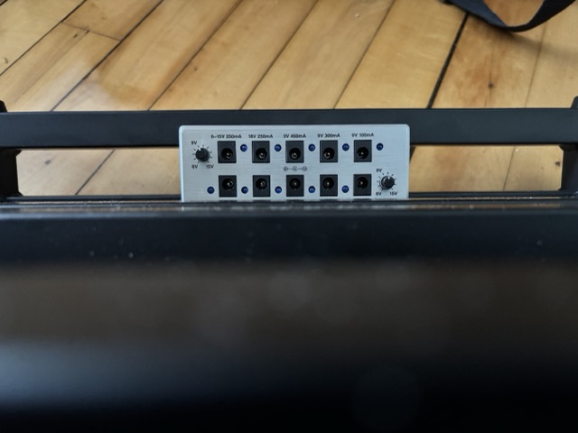
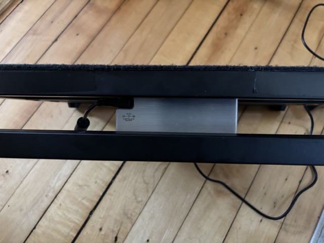
And a view from the back of the pedalboard showing that there’s enough clearance to allow the power cable to be unplugged if needed.
So this is everything- 6 screws and a lot of measuring to make sure the clearances all would work. The big takeaway would be to get a 0.125″ or 0.250″ at the most for the aluminum plate thickness and use washers or spacers to give the clearance needed to reach about 1/2″. Without that clearance you won’t be able to plug power cables into the power outlets of the ISO-Brick. If using a thinner plate you’ll also want to get shorter M4-0.7 x 60mm screws for the power supply itself, likely 55mm depending on the thickness of your plate.
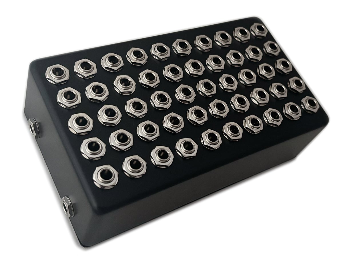
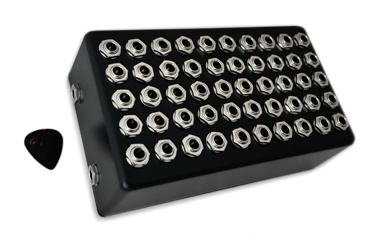
Inspired by a group of programmers that attempted to build The Worst Volume Control UI, we’ve come up with the worst volume pedal design. Does it work? Yes! Does it solve a problem anyone has? No! Rather than a volume knob we’ve gone with fifty jacks starting at 98% and dropping in 2% increments down to completely muted.
This device measures in at about 7.5″ x 4.5″ and weighs over 2 pounds due to the 52 jacks. The enclosure was an accidental order nearly 20 years ago and being an awkward size it’s been sitting and waiting for the right project. The top face happens to have the perfect amount of space for 50 jacks and the unusual height leaves plenty of clearance for the jacks to mount vertically. The completely passive design means no power supply is needed. I’m not entirely sure what will happen to this but one thing for certain is this will never be a production device from us.
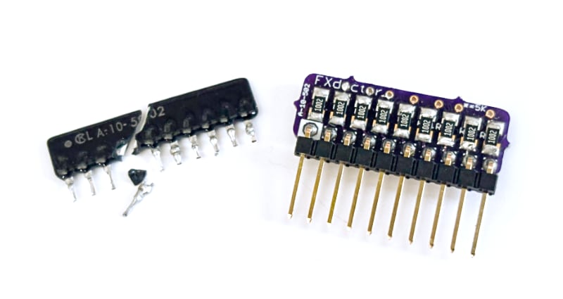
The Digitech PDS series is the most common pedal that we see in for modifications and a recent one came in with a mystery distortion on the delayed signal. After a closer inspection we found the LA-10-502 resistor network was physically cracked and needed to be replaced. Unfortunately this part is long out of production and even a modern equivalent was difficult to find in a SIP package.
This part is a network of resistors combined into one package used in conjunction with some chips to convert the analog signal to digital and back again to analog. Since there’s a good amount of space available inside of the pedal we were able to build our own direct replacement for this part to repair the pedal and have available for future repairs.
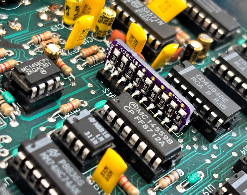
Above is a close-up of the chip showing that there was no saving it. Below we can see the replacement installed and working as expected. It’s a bit taller than the original and could be mounted closer to the PCB if needed but the PDS circuit board had plenty of clearance between components allowing us to build a PCB that’s easy to assemble and install.
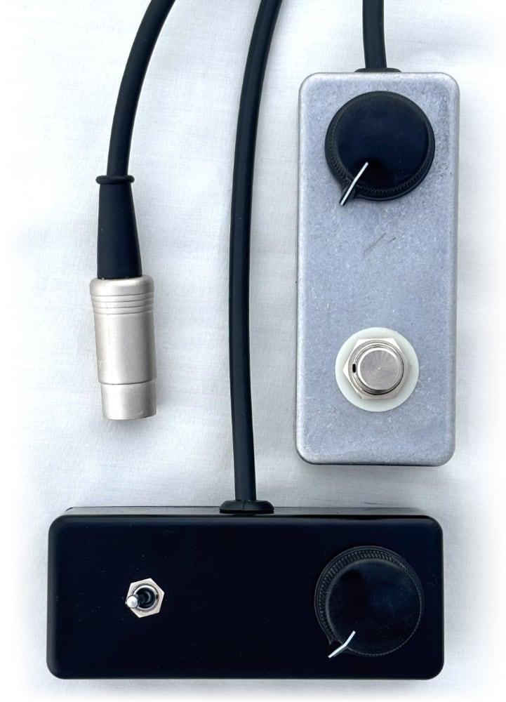
This is a fourth post of our Shin-ei Uni-Vibe controller – a mini option to replace the massive rocker footswitch that the original uses. Above we have two formats:
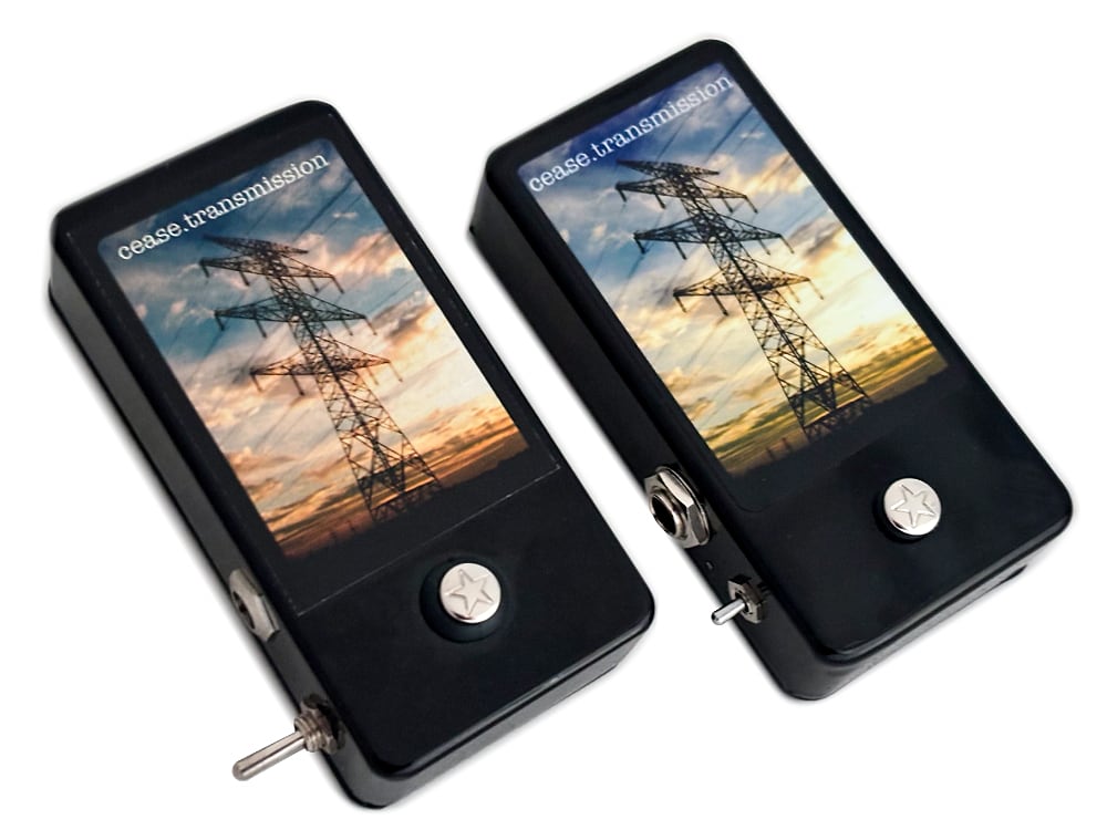
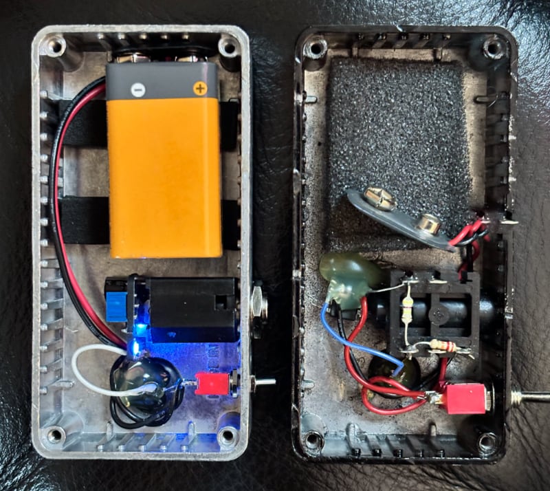
In around 2006 we started offering the cease.transmission noise maker / oscillation device on our website. You put your finger on the touchpad and it outputs a tone. These were time consuming to make but we kept them on the website for almost 10 years because they filled a hole in our lineup of oddball noise devices. Now revisiting this circuit nearly 20 years later we have a much different pedal building landscape in terms of PCB and parts availability. The original device had no PCB and everything was wired point to point. The 2025 revision has a tiny PCB mounted to the back of the output jack and also a volume trimpot as well as a tiny power LED that you can peep through a small hole drilled in the side of the enclosure. Otherwise this is the same circuit two decades later and even uses the same batch of touchpads that we ordered back in the day.
These will be available in small batches and may not always be listed on our products page.
2025 prototype on the left; 2012 prototype on the right
The Electro-Harmonix Freeze Sound Retainer has always been a favorite and a pedal that sits on my personal pedalboard. It’s a really unique effect that can add a lot of texture for such a small package. The biggest complaint by far has always been the footswitch on this pedal; It uses a momentary switch that has a physical click when depressed. This can be particularly annoying if you’re repeatedly triggering the pedal. We’ve offered an Overhaul Mod to replace the footswitch with a soft touch footswitch and also a 1/4″ jack so you can use your preferred remote footswitch. Connecting a sustain pedal designed for a digital piano immediately became my preferred way of using this pedal but let’s take it one step further and rehouse the entire EHX Freeze’s circuit board inside of the sustain pedal.
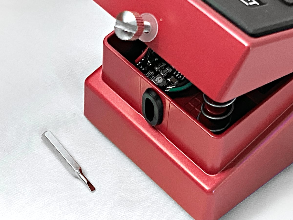
The rehousing started off with trimming down the Freeze’s PCB to fit into the new enclosure. The sustain pedal is large but the inside has a massive spring and hinge mechanism so there isn’t as much room as it appears. The casing is plastic so the inside needed to be shielded with copper tape. After that we’re installing a DC jack on back, 1/4″ jacks on the side for in and out, volume on the side, and a red LED on top. This pedal had the toggle switch removed and has been wired to permanently be in the “Slow” mode which allows the sampled sound to slowly fade out. Otherwise there are no surprises or add-ons as the goal for this project is to have a simple pedal that does one thing very well.
I look at this rehousing and I think this is how the sound retainer circuit should have been packaged. The smooth, long taper of the sustain pedal feels natural and doesn’t introduce mechanical noise that might be picked up by microphones when recording an orchestral string instrument. Rehousing everything into one package not only saves space but also simplifies setup. This rehousing is definitely not for everyone, but I think I’ll see some people that can appreciate the modifications!
And now for the bad news: this project was incredibly time consuming and isn’t something that we’ll be offering again. It was a fun project but it’s not a good business offering.
It’s been about 12 years since our last Mu-Tron III Rehousing blog post. Since then we’ve made a few refinements and now have what we’d consider a standard combination rehousing and overhaul. The goal is to shrink down the footprint of the original pedal while also adding in modern features from our standard Mutron Overhaul modification.
We start off this mod by taking the circuit board out of the stock enclosure and removing the multi-colored rocker switches. The circuit board is then installed into the new enclosure measuring about 4.7″ x 5.7″ now with the in and output jacks on the sides instead of the back of the pedal. DC input jack just barely visible on the left side as well.
For modifications we go with the three big ones that make up our Overhaul mod: 1. Install a new footswitch that’s wired for true bypass and put in a status LED that lights up when the pedal is active. No more turning the gain knob and having it adjust your bypassed volume level once the pedal is converted to true bypass. 2. Install a standard 9V DC jack and a voltage inverter so you no longer need to track down an original 18V power supply. Unfortunately after the rehousing there’s no longer a 9V battery option due to space limitations in the casing. 3. We add a sensitivity knob to fine tune how wide the filter opens. You can still use the stock Gain knob to roughly adjust the volume and then dial in the filter’s sensitivity separately without impacting the overall volume. The sensitivity knob is designed to complement the Gain knob.
So there we have it. Same original tone, some nice-to-have updates, some expanded controls, all in a smaller package.
My favorite part of running a custom shop is when I have time to work on these oddball projects. We’ve had a few similar prototypes over the years but decided to finalize the design in what you see on this page. The goal was to create a circuit that triggers when physically tapped anywhere on the casing. Then we can tie that trigger into existing circuits such as turning a pedal on or off (as shown below) or functioning as a replacement for a tap tempo pedal.
So you might be wondering what the point of this is- why not just press the on/off switch on the Boss pedal shown below; or why not just use a standard momentary switch for tap tempo? The simplest answer is preference. Footswitches work great for feet but can be clunky and imprecise for musicians sitting at a desk, keyboard players, or anyone using their hands to activate. Tapping a pad is easier to tap on beat than pushing a foot switch. Drummers can trigger a device by tapping the device with a drum stick. This device is for a very specific purpose and likely doesn’t apply to most guitarists.
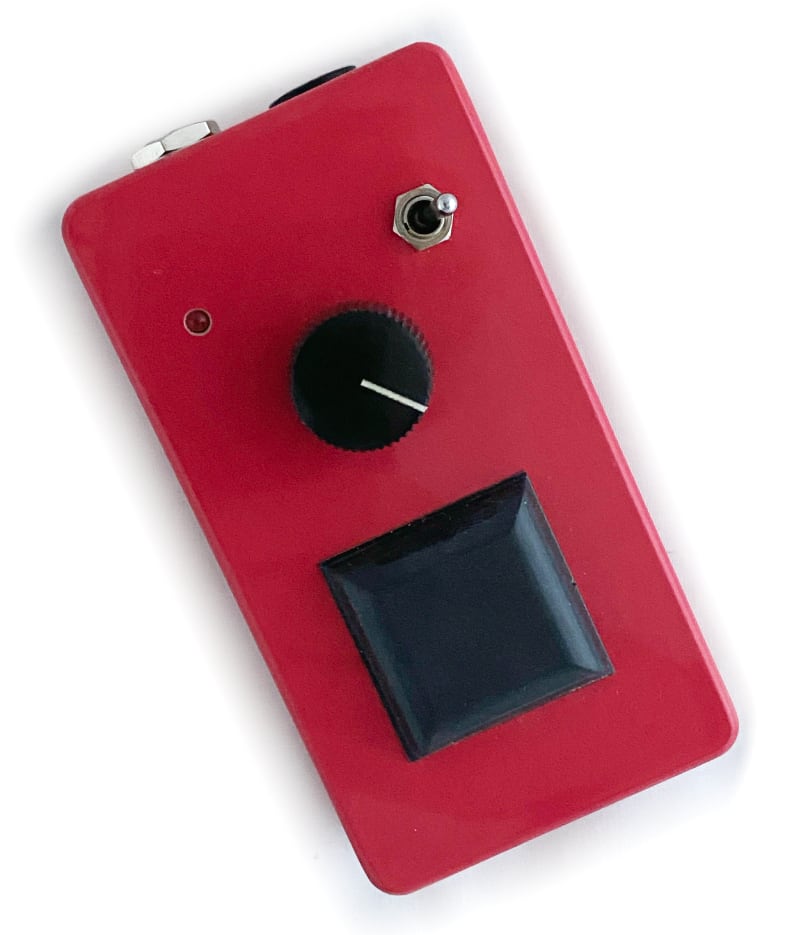
A quick run down of the controls on the red tap tempo prototype: • Big Rubber Pad for tapping • Sensitivity knob – controls how hard you need to tap to trigger the device • Red LED – indicates when the device triggers. Great for troubleshooting and confirming the device is firing when expected • Override Toggle Switch – this functions as a backup for when tapping isn’t needed. This momentary toggle switch will short the tip to ground like any traditional tap tempo switch. • Output jack – 1/4″ out to connect to control device • 9V DC jack – very low power draw (a few mA) but does require external power.
Below is what this tap tempo prototype looks like when tied into the bypass switch of a modified Boss NF-1.
A quick function check on a modified NF-1
This circuit board was then trimmed down to be smaller than a 9V battery and fit in the battery compartment of any standard pedal. Below is an install of the circuit to control the bypass of a Boss DM-2W. The pedal should only activated when the pedal itself is tapped and should not be sensitive enough to trigger on or off when the jacks are bumped.
This pedal should activate only when the case it tapped and NOT when the jacks are tapped.A peek at the circuit board with the smallest sensitivity adjustment trimpot installed in the battery compartment.